Tomographic Imaging Software
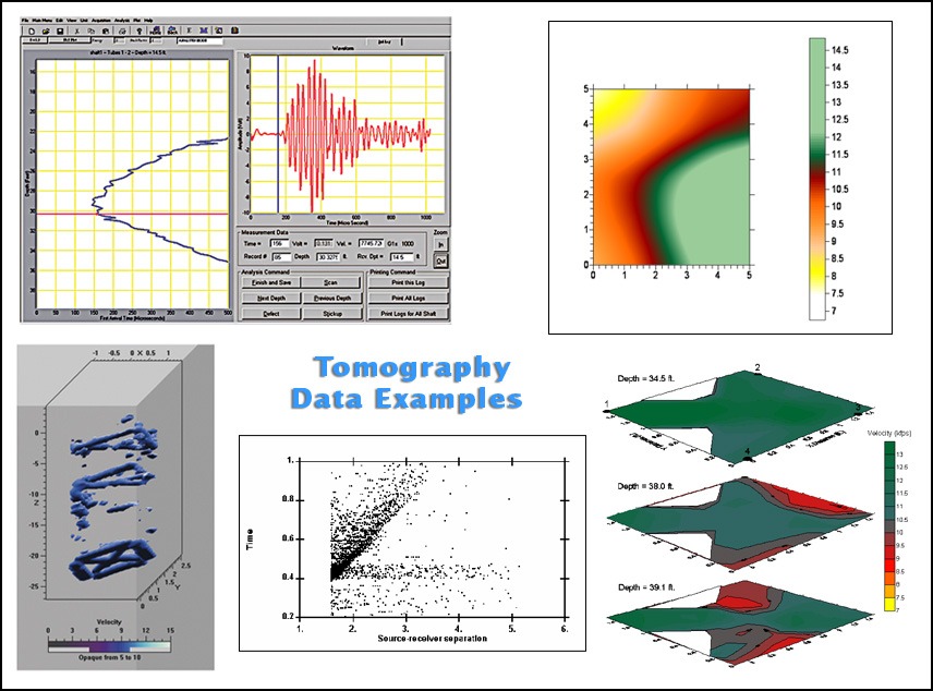
Tomographic velocity images are powerful analysis tools used to characterize the size, shape, extent, and severity of potential defects and anomalies.
Tomographic Imaging Software (TOMO) is most commonly used in conjunction with the Crosshole Sonic Logging, Ultrasonic Pulse Velocity, and Crosshole Seismic/Downhole Seismic methods.
This type of testing/processing is often deployed to illuminate the extent, location, and severity of a defect found with previous testing. This methodology can, however, be used in instances when the user requires a 2-D/3-D velocity image of the medium in question (e.g. soil body velocity structures).
NOTE: Tomographic software can be used with any Windows computer.
Materials Tested:
- Bridge Substructure
- Cemented Radioactive Wastes
- Concrete Drilled Shafts
- Dams
- Diaphragm Walls
- Masonry
- Mat Foundations
- Mass Concrete Placements
- Slurry Walls
- Structures
- Soil/Rock
- Wood
Test For:
- Cracks
- Honeycomb
- Voids
- Uncured or Weak Concrete
- Soil/Water Intrusions
- Soil/Rock Moduli
- Soil/Rock Velocity Profiles
Meets ASTM:
- Depends on system
Meets ACI:
- Depends on system
Key Features & Specifications
| Inversion program can perform travel time and attenuation tomography | Software packages easily interface with each other providing the user with a valuable visual tool |
| Anisotropy can be specified for each point of the grid allowing for more accurate models | Accurately characterizes size, location, and severity of defects |
| Ray paths can be both straight and curved allowing for more accurate models | 2-D/3-D display software is completely customizable to meet the user’s graphical needs |
| Processing tools capable of identifying multiple defects | Display software can create a variety of images, including movies for visualization aids |
Options
| Tomo-1 Option: Available for the Following Systems |
Advantages |
| Crosshole Sonic Logging (CSL) + Tomographic Velocity Imaging |
Crosshole Tomography (CT) testing and analysis is used to generate velocity images of anomalies between tested tube pairs in order to better judge the extent and severity of defects. With the CSL-2 Tomo software, the CT method uses data from multiple CSL logs at different source-receiver height offsets to generate 2-D image slices of the material between a pair of access tubes in a shaft. When data is collected between multiple access tubes, the data sets can be combined to create a 3-D image model of the interior of the shaft concrete, delineating defects. |
| Ultrasonic Pulse Velocity (UPV) + Tomographic Velocity Imaging |
Ultrasonic Pulse Velocity (UPV) Tomograms are generally used to map out the location, extent, and severity of defects in structural members. This method takes advantage of the multiple crossing test paths generated by combining direct, semi-direct, and indirect UPV testing. This data, once picked for First Arrival Time (FAT), is used to generate 2-D or 3-D velocity images. This data and model can often be a valuable resource when repairs are needed on structural members because it provides the information necessary to isolate the problem. Sonic Pulse Velocity (SPV) data is used to provide velocity images of massive dams, bridge substructures, etc. |
| Crosshole Seismic/Downhole Seismic (CS/DS) + Tomographic Velocity Imaging |
The tomographic velocity images created from data acquired during Crosshole Seismic/Downhole Seismic (CS/DS) tests are generally used to look at the material properties of soil/rock. More specifically, this technique is ultimately useful to image the lateral/vertical changes in material properties for a more complete site characterization. This method uses compressional or shear wave arrival time data collected at different source-receiver height offsets to generate a 2-D image slice between boreholes. When more than two boreholes are available, then the testing can be conducted such that a 3-D image model of the material between multiple test tube pairs can be generated. |
Hands-on training is available for all of our NDE test methods at our Wheat Ridge, Colorado (USA) location, which is a suburb located approximately 15 minutes northwest of downtown Denver. Training may be available at your location by one of our agents/engineers upon special arrangement.


