Crosshole/Downhole Seismic
(photo gallery)
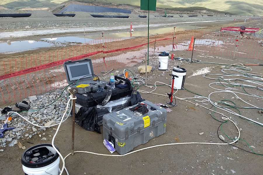
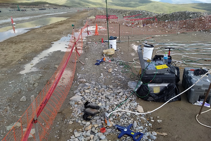
Crosshole and Downhole Seismic (CS/DS) investigations provide information on dynamic soil and rock properties.
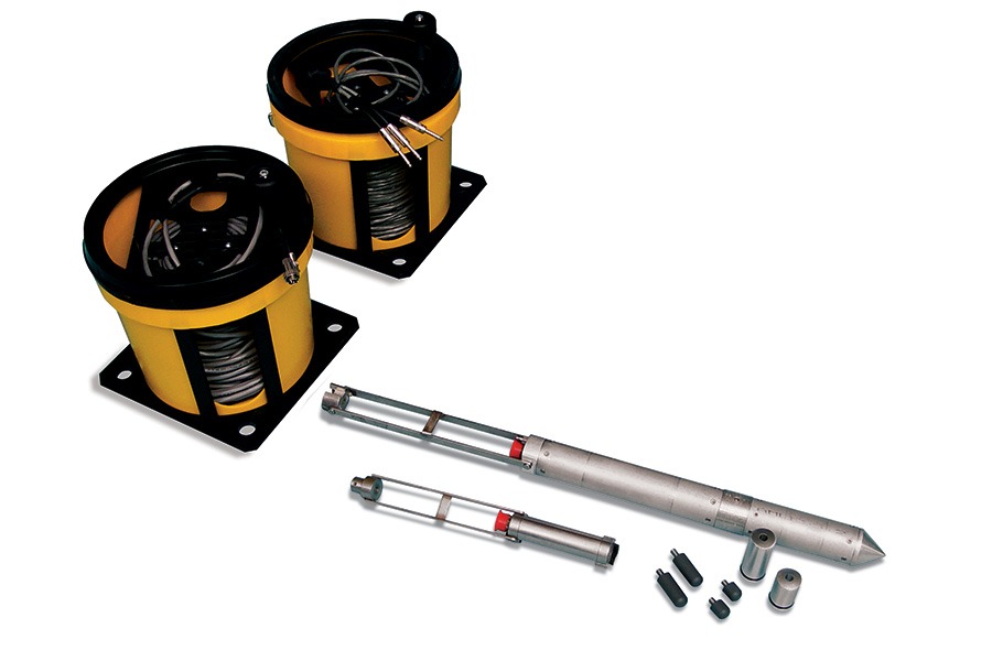
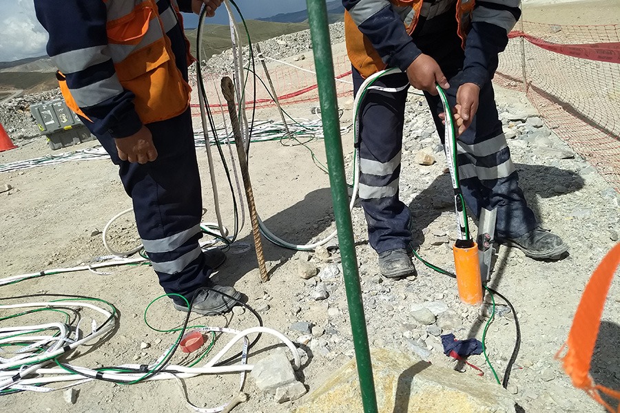
The Crosshole Seismic (CS) system and method determine shear and compressional wave velocity versus depth profiles. From these measurements, parameters, such as Poisson’s ratios and moduli, can be easily determined. In addition, the material damping can be determined from CS tests. These dynamic soil and rock properties are often utilized for earthquake design analyses necessary for certain structures, liquefaction potential studies, site development, and dynamic machine foundation design. The most complete version of this downhole system, as manufactured by Olson Instruments, is comprised of a borehole source capable of generating shear and compressional waves and a pair of matching three component triaxial geophone receivers. These instruments are lowered to the same depth in boreholes set at ~ 10 ft (3 m) apart in a line. The instruments are coupled to the side of the grouted borehole inclinometer casing, allowing for the detection of shear and compressional waves as they pass between the receivers.
Tomographic Imaging Software, which is sold by Olson Instruments, allows the user to perform tomographic inversions of CS seismic velocity data which provides 2D or 3D shear or compressional wave velocity images of soil and rock. (Note: Optional Tomo software is available for the CSL, UPV, and CS/DS add-on test methods.)
Data Platform Required, Sold Separately
 |
Freedom Data PC |
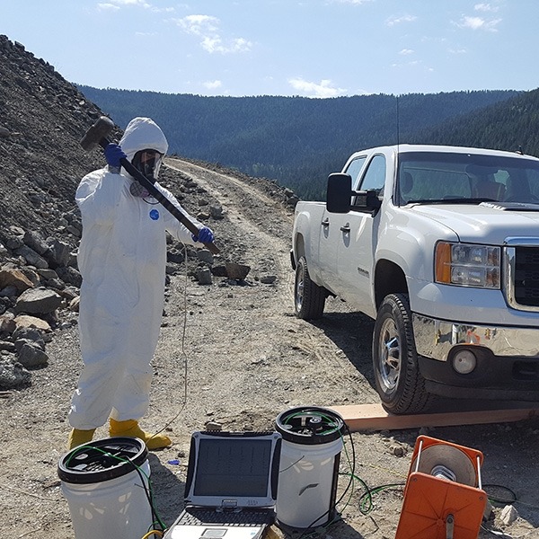
The Downhole Seismic (DS) investigations are similar to CS investigations, but require only one borehole to provide shear and compressional velocity wave profiles. The DS method uses a hammer source at the surface to impact a wood plank and generate shear and compressional waves. This is typically accomplished by coupling a plank to the ground near the borehole and then impacting the plank in the vertical and horizontal directions. The energy from these impacts is then received by a pair of matching three component geophone receivers, which have been lowered downhole and are spaced 5 to 10 ft (1.5 to 3 m) apart.
Applicable On:
- Soil & Rock for Seismic and Vibrating Machine Foundation Design
Test For:
- Image Voids, Solution Caverns, Washouts with Tomography
- Locate Faults, Fractures
- Seimic Shear & Compressional Wave Velocities
Meets ASTM:
- D4428
- D4428M-07
- D7400 (DS)
Meets ACI:
- N/A
Key Features & Specifications
| Real-time waveform display while testing | Accuracy and resolution for the CS method is constant for all test depths, whereas the accuracy and resolution of the DS method decreases with depth |
| P-SV source used in CS tests can impact in the vertical, transverse, and radial directions | Correlation between CS and Spectral Analysis of Surface Waves (SASW) tests on soil sites showed that the values from both tests typically compare within 10-15% |
| CS method is the most accurate method for determining material properties of rock and soil sites | Acquisition and processing software is easy to use, yielding fast and accurate results |
| Thin layers, which are often invisible to surface methods, can be detected with CS/DS investigations | Sources and receivers can be oriented with inclinometer casing dummy probes |
CS-1 Model
| Description: | Test For: | Applicable On: |
| The CS-1 Model includes one triaxial geophone and all necessary accessories for crosshole seismic testing when used with a downhole source. (This system is only sold in combination with a P-SV source.) |
|
|
CS/DS-2 Model
| Description: | Test For: | Applicable On: |
| The CS/DS-2 Model is the base model for Crosshole or Downhole Seismic Testing. This system includes two triaxial geophones and all necessary accessories for crosshole seismic testing when used with a downhole source. An accelerometer is also included to trigger data collection for downhole seismic testing. (A P-SV source is required to perform crosshole seismic testing.) |
|
|
Optional PS-V Source
| Description: | Test For: | Applicable On: |
The PS-V Source allows for accurate and rapid triggering in crosshole seismic testing by directly impacting the borehole casing.The P-SV source is configured for use with the CS-1 and CS/DS-2 models mentioned above. Most time-effective downhole source system available.
|
|
|
Optional TOMO-1 Software
| Description: | Test For: | Applicable On: |
| Allows the user to perform tomographic inversions of CS seismic velocity data which provides 2D or 3D shear or compressional wave velocity images of soil and rock. |
|
|
Hands-on training is available for all of our NDE test methods at our Wheat Ridge, Colorado (USA) location, which is a suburb located approximately 15 minutes northwest of downtown Denver. Training may be available at your location by one of our agents/engineers upon special arrangement.